By Kathy Ziprik
Add curb appeal the easy way with a DIY-friendly railing kit.
Contractor Steve Roth recently purchased an old single-family home in Ohio to transform into a duplex. The original home featured a small rear entryway with a crumbling concrete step.
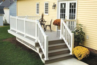
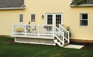
With a vision in mind for a more spacious, family-friendly exterior, Roth exchanged the single entry with a double French door to add light into the home and provide fast access to a new deck. Installed in just one afternoon, the composite deck and rail system is made to last with minimal upkeep.
Roth constructed the 8-by-14-foot deck on top of a concrete base with a wood subfloor. He added a QuickRail synthetic railing system with newel posts from Fypon on top of the deck and Fypon urethane moulding to trim out and finish the project.
“My research showed that the multi-layered PVC composite formula in the QuickRail system stands up to harsh weather,” says Roth. “The system comes with a white finish that never needs painting and the product will never decay, warp, fade, chip, splinter or rust. That’s the kind of easy-maintenance product I wanted on this house.”
For the project, Roth selected the 36-inch high QuickRail rail kit with square spindles and used six 6-foot kits. Each kit includes the top and bottom rails, spindles, brackets, crush block and stainless steel screws. The company also has 8-, 10- and 12-foot kits. A stair kit, used to connect the rail system to steps leading to the back yard, includes similar products. For this project, two stair kits with slopes of 30 degrees were used. Fypon offers the stair kits to accommodate 24- through 40-degree slopes.
To unite the rail segments and establish the outline for the rail system, Roth first installed the QuickRail newel posts. Each QuickRail post kit contains a 4-by-4-inch square post, structural post mount, post kit base, taper cap, threaded rod, 3-by-3-inch square plate with 1/2-inch hole, and a variety of appropriate washers, lock washers, hex nuts and stainless screws to complete the installation.
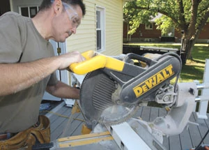
Prior to starting the project, Roth pulled together the tools recommended by the manufacturer: tape measure, circular saw, power miter saw, screwdriver, cordless drill, wrench, level and protective eyewear.
“There were no surprises or real challenges to this project,” says Roth. “It’s really a quick and easy project and I can see any homeowner tackling this with professional results.”
Newel Post Installation
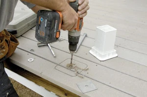
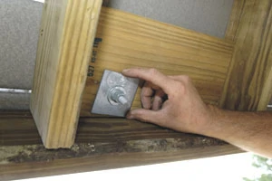
Step 1 – To start, Roth added blocking between the joists directly under the deck surface to ensure a solid fit for the newel post. Then he drilled a 1/2-inch hole through the deck surface and joist block.
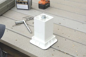
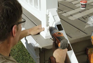
Step 2 – After aligning the center hole on the post mount with the hole in the surface, Roth inserted a threaded rod with one 1/2-inch washer, a 1/2-inch lock washer and a 1/2-inch hex nut on the top in that order.
Step 3 – Roth then slid the 3-inch square plate flush with the blocking he had installed onto the threaded rod under the mounting surface, followed by a washer and hex nut, leaving approximately 1-inch of threaded rod beyond the end of the hex nut. He tightened the hex nuts until the post mount was secure.
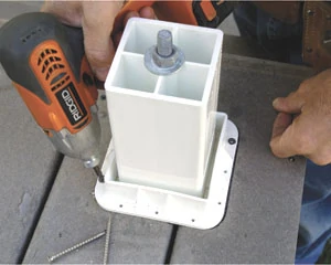
Step 4 – To further secure the post mount, use two of the stainless screws provided on each side of the post mount in the predrilled holes.
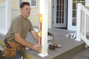
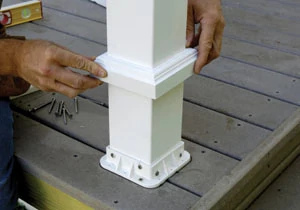
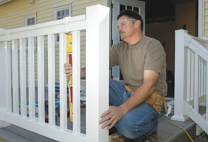
Step 5 – Roth next inserted the post into the post mount and made it plumb.
The newel sleeve will sit comfortably inside the post mount. Once you get the newel sleeve plumb, you can lock it into place with the two screws on each side of the newel post sleeve.
He was careful not to drill into the middle of the post mount and also positioned the screws at different heights so that the screws did not overlap one another.
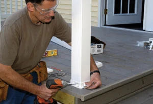
Step 6 – Next, Roth slid the post kit base trim collar down the post and over the post mount.
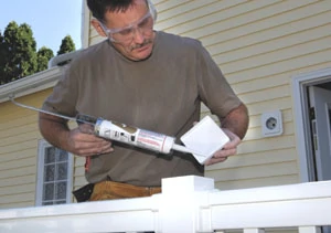
Step 7 – As a final step, the taper cap was attached to the post sleeve with PVC glue that he purchased locally.
After completing these steps, Roth proceeded to install the railing system.
Railing Installation
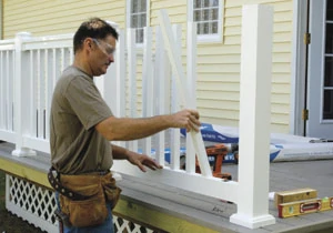
Step 1 – Roth measured the inside opening between the mounting surfaces to verify that the opening was not wider than the length of the rails provided.
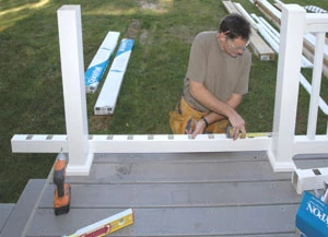
Step 2 – The bottom rail was laid beside the mounting surfaces with the spindle holes facing up. The rail should extend past the mounting surface on each side. Place the first spindle hole on each end of the rail the same distance from the mounting surface.
Step 3 – When properly positioned, Roth marked both ends of the bottom rail and cut to length.
Next, the top rail was laid beside the bottom rail, aligning spindle holes. Both ends were marked and another mark was made 1/4-inch in toward the center of the top rail from the marks transferred from the bottom rail. This allowed for some movement of the top rail to level the spindles later in the process. Lastly, the top rail was cut to length.
Step 4 – Roth located the crush block and used the following formula to determine the length: Desired clearance from bottom rail to deck + 3-1/4 inches = length of crush block. (The spindle lengths are sized for a traditional 2-inch clearance from bottom rail to deck.) Once the block was trimmed, Roth inserted the crush block into the precut hole on the underside of the bottom rail.
Step 5 – Bottom brackets were slid onto the bottom rail. Then the bottom rail was placed into the opening with Roth making sure the rail was level. With brackets centered on the mounting surface, attach with the provided 2-inch screws. When installing bottom rail brackets, make sure not to over-tighten screws. If the screws are over-tightened, flaps may not stay closed on the brackets.
Step 6 – Roth inserted the square spindles into the precut holes in the bottom rail.
The precut holes are spaced to adhere to the 4-inch rule to meet ICC code compliance for balustrade systems.
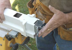
Step 7 – The top rail bracket covers were slid onto the top rail. The metal top rail brackets were slide into the ends of the top rail.
Roth placed the top rail on spindles inserting the spindles one at a time while holding at an upward angle and then making certain the rail was flush on all spindles.
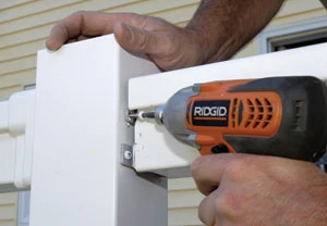
Step 8 – Finally, Roth centered the top rail metal brackets on the mounting surface, making sure that the top rail was aligned above the bottom rail.
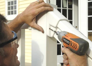
He attached the brackets with the provided 2-inch screws after predrilling.
Step 9 – The spindles were leveled vertically by adjusting the top rail.
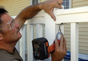
Roth secured each end of the top rail by using two 3/4-inch pan head locking screws that were provided in the kit. Holes should be predrilled through both the rail and metal bracket 1/2 inch from the end of the rail. The hole for these screws must be pre-drilled using a 1/8-inch drill bit.
Step 10 – The bracket covers were slid over the metal brackets and secured in place using the provided 3/4-inch flat head locking screws.
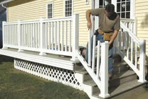
To add the stair rails on both sides of his steps, Roth followed similar procedures for the straight rail installation, except working on a 30-degree slope.
For this stair application, the square spindles were spaced a nominal 3-1/8 inch apart. Stair Top Rail and Bottom Rail brackets and bracket covers were used to connect the stairs to the straight deck railing and to the post at the bottom of the stairs.
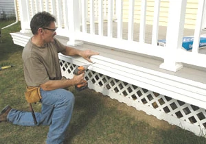
To finalize the project, Roth added weather-resistant urethane moulding around the exterior edge of the deck. He selected a profile traditionally used on door and window frames because of the detailed dimensions of the piece. After applying premium millwork adhesive to the back of the piece and fitting it in place, the moulding was secured with stainless steel screws to the deck.


