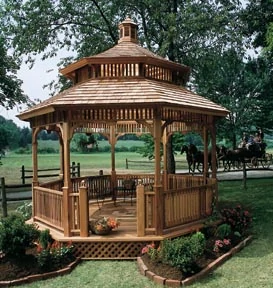
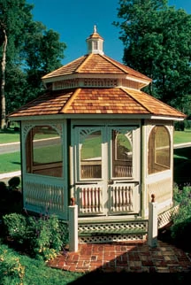
A cool, peaceful retreat from the summer heat, a gazebo is a stylish feature of many of today’s lawns. Gazebos can provide shelter for an outdoor hot tub, function as a poolside picnic area, an exercise room or simply a relaxing way to enjoy the outdoors. In a yard or garden a gazebo is a picturesque setting for dinner parties and weddings, providing a distinctive and elegant look to the landscape.
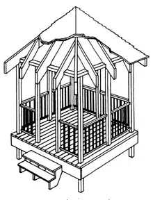
Whatever the style or use of a gazebo, smart construction is a prerequisite. Many companies offer a variety of modular gazebo kits. However, a seasoned handyman may prefer to build his own from scratch. The building plans explained here are for a modest 8-by-8-foot square gazebo, but structural gazebo designs, amenities and materials greatly vary from builder to builder. And choosing the proper building materials is a crucial first step to achieving a striking appearance while standing strong in the face of harsh weather.
Over the past few years, a number of alternative outdoor materials have entered the market for outdoor construction, including plastic materials, wood-plastic composites and exotic hardwoods. Yet pressure-treated lumber is still the most preferred material for outdoor furnishings, offering a classic look, as well as protection against decay, termite attack and other outdoor elements. However, with the future condition of the gazebo relying greatly on its material performance, chemically treated wood may be a smart upgrade to ensure years of long-lasting durability despite a barrage from the brutal elements. New options include wood featuring integrated water repellent. And new, stronger preservatives strengthen the wood while remaining safe to the environment, eliminating the health concerns associated with arsenic-treated lumber. A safe, durable choice may be lumber treated with such modern preservatives as ACQ (Alkaline Copper Quarternary), reported to be the most widely used, non-arsenic, non-chromium, water-based wood preservative in the world. For years of reliable use, think long-term durability when spec’ing materials for a gazebo.
Once the building material is selected, take note of the shopping list of materials for the following gazebo plans. Whereas it’s quite a truckload at the lumber outlet, the project will be well worth your effort and is not as difficult as it looks. Simply break the project into phases with a certain goal for each phase. Work toward erecting a basic gazebo with the idea that the decorative trim and add-ons can be saved for a rainy day, figuratively speaking.
Materials
Pressure-Treated Lumber:
9 pcs. 4” x 4” x 8′ 5 for posts and four for roof beams (cut)
4 pcs. 4” x 4” x 12′ Corner posts
5 pcs. 2” x 8” x 8′ Floor joists
1 pc. 2” x 8” x 12′ Bridging and blocking
7 pcs. 2” x 10” x 8′ 6 for deck and 1 for step treads
23 pcs. 2” x 6” x 8′ 7 for flooring, 2 for step treads and 4 for (C) rafters
8 pcs. 2” x 6” x 10′ 2 each for (A), (B), (D) and (E) rafters
3 pcs. 2” x 4” x 14′ Rails
1 pc. 2” x 4” x 8′ Rails
1 pc. 2” x 4” x 10′ Steps and nailer
8 pcs. 2” x 2” x 16′ 1 for bond timber and sevenfor pickets – 42 pcs., 30” long
4 pcs. 1” x 6” x 10′ Across ends of rafters (fascia)
5 pcs. 1/2” x 4′ x 8′ CD plywood for roof sheeting
(Note: 4-6 pcs. 1” x 4” x 12′ lumber will be helpful for bracing, etc. Six bundles of square shingles, a corresponding amount of felt paper and roofing tacks are needed for finishing the roof. Instructions for installing the shingles should be included with the bundles.)
Hardware
10 Galvanized joist hangers
8 pcs. 1/2” x 6” Zinc-plated lag bolts
10 pcs. 1/2” x 5” Zinc-plated lag bolts
16 pcs. 1/2” x 3” Zinc-plated lag bolts
16d Hot-dipped, galvanized nails for framing
8d Hot-dipped, galvanized nailsfor pickets and fascia
8d Cement-coated nails for plywood
Various wood screws
Gazebo Plans
Phase 1: Foundation
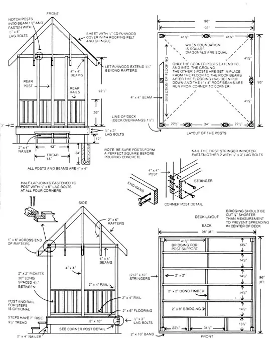
Using stakes and string, square up the area on which the gazebo will be built. Pull a string from one corner to another corner. Ninety-three inches should be the distance between each outside edge of the gazebo’s supporting posts. Make sure the line is level and mark the corner. Continue this process for all four corners ensuring each measurement is square and level.
Before setting the 4-by-4-inch, 12-foot-long corner posts, check local building codes for the depth of footings required and for other construction details. Be sure to avoid underground pipes and wires. Typically, holes for concrete footings should be at least 24 inches deep. Make sure the posts are deep enough to avoid heaving during freezing and thawing temperatures.
Locate the post positions and dig the holes, 12 to 16 inches in diameter. Shovel in a 6-inch bed of gravel and tamp it down, or fill the hole with 3 inches of concrete and allow it to dry for 24 hours. Top the concrete with 3 inches of gravel to allow for drainage.
Set the posts using a level to ensure they are plumb, then pour concrete around the posts to anchor them. Use strips and stakes to keep the posts in plumb position while the concrete dries (again, allow at least 24 hours for drying). It may help to construct some simple bracing to keep the posts in position overnight. If you choose to add concrete “collars” around the bases, be sure to taper the collars away from the posts to allow drainage.
Phase 2: Decking
Use a line level on a mason’s string to establish a level point on each post, 12 inches from the ground (at the beginning point). Depending on the fall and swell of the plot of land, the measurement will vary from the ground somewhat at each post. The primary concern is that all four notch-points are level. Leave the bracing in place to absorb some of the shock of the hammering. Notch the posts to receive the first stringer (see the diagram on page 38 for notching positions). Attach the 2-by-10-inch stringers, securing them with 3-by-1/2-inch lag bolts. Notice that the two sides of the gazebo are built with double stringers. Add support by nailing a 2-by-2-inch bond timber to the inside of each double stringer, flush with the bottom.
Next, nail the floor joists in as shown in the diagram. Attach them from the end with 16d nails or wood screws. Install the joists flush and at right angles to the double stringers, ready to support the decking. Place galvanized joist hangers around the joist ends, attaching them with 1 1/4-inch wood screws. Use all available mounting holes on the hangers to secure the joists.
Then, add the bridging between the floor joists according to the diagram (lower, right-hand corner on page 38). Note that the first joist and front beam are supported by double bridging spaced 34 1/2 inches apart. The double bridging will support the 4-by-4-inch beams that will frame the front entrance.
Lay the deck boards running from front to back, or perpendicular to the joists, notching the boards as necessary to allow the corner support beams to run up through the deck. Use a 10d nail as a spacer between the boards. Attach the decking boards to the floor joists with 6 1/2-inch wood screws. Predrill starter holes for the screws to prevent the wood from splitting.
Always place the lumber with the bark-side facing outward (or up) when building the surface of the deck. This will help the surfaces to resist “cupping.” See the growth rings on the ends of the lumber to make sure the bark-side of the board is up.
Next, add some simple three-stringer steps. The steps shown have a 7-inch rise, a 9 1/2-inch tread depth and a 45-inch tread width.
Phase 3: Railing
Notch the roof beams with half-lap joints. Fasten the notched roof beams to the posts with 6-by-1/2-inch lag bolts at all four corners, making sure they are square and level. Set the other five 4-by-4-inch posts and nail them into the floor and beam after ensuring they are plumb. The additional five posts should be positioned directly above the floor joists (or double front bridging) to ensure proper support. Also, make sure the posts are evenly spaced, plumb and in line with the original supporting posts to accept the string of rails and pickets to be installed. Hardware stores offer brackets to assist mounting the posts to the deck.
Where the additional posts meet the roof beams, cut 1 1/2-inch notches into the posts and fasten to the beams with 5-by-1/2-inch lag bolts.
Next, cut the 2-by-4-inch boards to length for the bottom railing and nail them between the posts, allowing 3 inches of space between the deck surface and the bottom edge of the rail. Complete the railing around the gazebo, except between the two front double posts framing the entrance. Once the bottom rail is in place, add the top rail, ensuring 30 inches of space between the top and bottom. Then install the 2-by-2-inch pickets, each measuring 30 inches and spaced at 4 1/2 inches between each picket. Fasten them in place with 8d nails or wood screws, predrilling pilot holes to prevent splitting.
Phase 4: Roof-Framing
Check to be sure the four corner posts are plumb and that the beams the rafters will be resting on form a perfect square. Brace the entire structure securely.
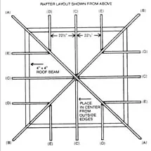
The rafters should be erected in order of their corresponding letters as depicted in Diagram R1: (A) first, (B) second, etc. The rafter measurements that are given here may require some adjustments, depending on variables such as actual lumber sizes, the accuracy of cuts and the squareness of the structure at this point.
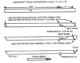
Rafter Pattern for (A) and (B) Hip Rafters
The easiest way to mark the lines to cut the rafters is to create a pattern tool to guide the markings. To create the pattern, start with a 2-by-6-by-24-inch block. On one end of the block, mark it 3 7/8 inches out of square, as shown below. On the other end, mark it 7 3/4 inches out of square. Draw lines from these points to the top corners of the block on each corresponding side. Cut these lines, removing the lower square corners of the block.
Next, nail a 1-by-4-by-22-inch strip along the top edge, centering it on the edge and overhanging the sides. From the end of the piece, the pattern should form a “T” shape. This top edge will serve as a lip to rest over the edge of the rafters and assist marking the lines to cut. As shown, make a mark 4 1/2 inches from the top corner on the edge of the 2-by-6 (the side where 3 7/8 inches have been trimmed away). Label this mark “seat” and label the edge just beneath the 2-inch strip “top.” Label the adjacent right-hand edge “foot.”
Using the “top” end of the pattern, place the tool over one end of the rafter board and mark 3 7/8 inches out of square using the edge as a guide. For rafter (A) measure 80 3/4 inches from this corner and mark. From this new point, use the left-hand edge to mark a second line, this time marking the “seat” point on the line as indicated by the pattern tool. Slide the pattern exactly 21 inches further toward the end and mark a third line, using the same “seat” edge of the pattern tool.
With the rafter in the same position, invert the pattern tool and align the guide strip along the opposite, lower edge of the rafter. Match the lower right-hand corner of the pattern (seat edge) with the third, last line marked on the edge of the rafter. Mark the rafter at the “foot” edge of the pattern so the new line intersects the second (or middle) line already marked. At the intersection of the seat lines, the “X” indicates where a bird’s mouth should be notched into the lower side of the rafter, allowing it to sit on a roof beam when installed. Cut both the marked ends of the rafters, with a 45-degree bevel cut on the “foot” end.
All cuts to be made on rafters (A) and (B) should be made squarely through the board, except the very end cut on the foot. At the end of the foot, mark 3/4-inch back from the square cut, then cut at a 45-degree angle. These angles will keep the bottom perimeter of the roof framing square. Rafters (A) and (B) need the 45-degree cuts made from opposite corners of the foot (see the roof framing corners on Diagram R1).
The (B) hip rafters are laid out the same way as the (A) rafters. The only difference is the first measurement: (A) 80 3/4 inches; (B) 79 5/8 inches. The 21-inch measurement does not change.
After one rafter is cut out, that rafter can be used as a pattern for the others. Remember to cut the (B) rafters 1 1/8-inch shorter in length from the bird’s mouth to the top cut. From the bird’s mouth to the foot, the measurements should be identical.
Pattern Block for Rafters (C), (D), (E)
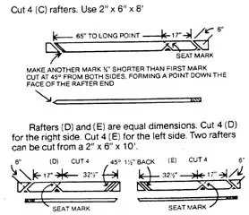
This block is also a 2-by-6-by-24-inch board with a 1-by-4-by-22-inch strip nailed on the top edge for a guide. Cut each end of the block at a 45-degree angle (or 5 1/2 inches out of square). Again, make a seat mark 4 1/2 inches from the top corner. Since both ends are identical, you may use either end for both the top and the seat cuts. Cut the rafters according to Diagram R5. Notice the varying widths: Rafters (C) feature 65 inches to their longest points; Rafters (D) and (E) feature 32 1/2 inches to their longest points. Seventeen inches will be the common “short distance” among all rafters (C), (D) and (E).
The top end of rafters (C) must be cut at 45-degree angles from both sides, forming a beveled point to intersect the hip rafters at the center of the roof framing.
The top ends of rafters (D) and (E) will need to be cut at a 45-degree miter where they will intersect the hip rafters. Rafters (D) and (E) must have the 45-degree angle cut from opposite sides (see Diagram R1).
Lay out rafters (A) on the ground, joining the top ends and making sure the bird’s mouths on each end will correctly match the diagonal corners of the roof beams. Recruit some assistance for installing the rafters. It may help to tack up temporary bracing for the rafters until the hip rafters are self-supporting.
Install the hip rafters (A) and (D), with rafters (C) intersecting them at the top. Space rafters (D) and (E) 22 1/2 inches from rafters (C).
Phase 5: Roofing, then Relaxing
With the rafters in place, the gazebo is ready for the roofing phase. Cut triangular sheets of plywood to cover the dimension of the roof and attach them to the rafters with cement-coated nails. The job of roofing and shingling requires six bundles of square shingles and a corresponding amount of felt paper and roofing tacks. Instructions for applying shingles will be included with the bundles.
Naturally, these building plans can be embellished or completely redesigned to suit different needs or decorative choices, and there’s plenty of room for fresh ideas. You may prefer decorative handcrafted trim, fascia, screening, a natural wood-stain finish or classic white paint. So be creative.


