

By Larry Walton
Build a patio shade cover without obstructing the view
Have you ever walked into form boards on a lumber rack? Or, have you abruptly met with the door frame of a truck cab because your view was obstructed by the bill of a ball cap? A similar obstruction is in place with many patio covers, which can keep you from seeing backyard views above the fence line.
The reason so many patio covers are built so low is because attaching to a ledger board below the gutters is a quick and easy way to attach the structure to the house. What starts out low on the house side gets even lower if the cover is sloped for water runoff.
A homeowner in our area was faced with an obstructed view when looking to add a shade cover over their back patio. The rear window provided a view of Roxy Ann Peak, which at 3,500 feet would be considered a mountain in some parts of the country. Roxy Ann is covered by snow much of the year and is a distinct feature of their backyard landscape. A low patio would make the mountain peak a distant memory.
The solution was to call in Brian Monroe to build a patio shade cover that attached to the roof above the gutter line. Monroe’s approach was to cut through the roofing material and anchor 4×4 posts to the roof sheeting, which required custom flashing around each post to redirect the water around the post holes and down the roof.
Here’s how they got the job done:
Step by Step
Monroe measured out from the house at both ends of the patio and used a chalk line to make sure the support posts were all in line and parallel to the house.

A post base with slotted hardware allows the base to be turned and moved from side to side around the anchor bolt. Once the post base is positioned and firmly anchored, the sides can be bent up to accommodate the 4×4 post. Be sure to use the correct type of nails to go with the post base. In this case, teco nails were used.

Plumbing and bracing the 4×4 post is a two-man job. One guy checks the level and makes adjustments while the other fastens the brace to the post.

A concrete form stake driven at an angle makes a good anchor for the 4×4 post braces. Each post should have two braces at 90 degrees from each other.

Each post can be marked using the laser level at a random elevation. From this mark, layout the cut marks on each post to keep the elevations consistent. Using a laser detector/receiver in conjunction with a laser level helps on larger layouts, especially where sunlight makes beams hard to see.
Monroe’s crew used a double set of 2×8 boards as beams connected to the 4×4 posts.
Deck screws hold the beams in place until stronger hardware can be installed. Notice that all splices in the beams are centered on the posts.

The crew used a layout line to project where the side of the house met the cantilever on the outside of the beams. They measured from the post to the layout mark so they could project the same location on the roof surface. Once they determined a point that matched the outside posts on the roof, they used measurements between the posts to mark the side-to-side locations of the other roof posts.

After leveling one joist from the outside beam to the roof, Monroe determined which course of roofing material would make a good post location to place the post on the rake of the roof (up or down the slope). After determining the location for the roof support posts, He used a utility knife to cut out the composite shingles down to the roof sheeting. A speed square bumped against the bottom edge of a course of shingles makes a good straight edge for cutting out the composite roofing to receive the roof support posts. He cut all the way through the roofing material to the roof sheeting so the roof post could be solidly anchored.

After taking his best guess at the pitch of the roof, Monroe cut a piece of the roof post material and checked for plumb with a short level.
The crew measured from the bottom of the leveled joist and marked the post, which represents the thickness of the beam that will sit on the post.

Monroe used sheet metal to cut out pieces for the flashing around the roof support posts. He used a section of 4×4 post to form the bends in the flashing.
.
It took four pieces of sheet metal to make up the flashing around each post. The flashing components must be installed in the proper sequence beginning with the downhill side pieces first and ending with the uphill on top. Once the crew decided the shape of each flashing piece, they repeated the process for each post.

Monroe used a chisel to separate the roofing components to receive the top piece of the flashing that would surround the roof support post.
The crew anchored the roof support posts through the sheeting and into the posts with screws driven from under the eaves. They used additional framing material as blocking to reinforce the rafter tails at each post location.

The beam on the house side of was made from doubled 2x material mounted on the posts. With the beams in place, the guys loaded the joists by sliding them to a waiting crew member on the roof.

The crew used a string line across the ends of the joists to get them in line. Fastening duties were handled by deck screws toe-nailed through each side of the joist into the beams.

The crew cut 45-degree bevels on the ends of the braces that prevent lateral movement in the structure.
Monroe initially tacked the braces in place with decking screws followed later with large lag bolts.
The post and beam structure with joists looks very much like a deck build.

The bolts run through the beams and the post with a bolt head and washer on one side and a washer and nut on the other. The crew cut counter bores in the beams to slightly recess washers for the bolts.
Some lumber cleanup was necessary for the lath pieces which run perpendicular to the joists. Operations like this are much easier to do on saw horses before installation.

When installing the lath, one of the first orders of business was to straighten some warped joists. The crew started by marking the layout used on the beams on the first pieces of lath and screwing the lath to the joists where the layout lined up easily. With the lath anchored at many of the joist intersections, they could use a large adjustable wrench to align the joist to the lath on the wayward framing members.

Monroe snapped a chalk line on the joists at the desired intervals for lath placement. Using layout lines helps keep everything straight and parallel.

With many of the lath pieces in place, the crew systematically nailed the lath to the joists at each intersection while watching the layout lines closely.

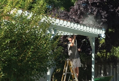
Monroe used an airless sprayer in one hand and a small roller in the other to apply the heavy bodied exterior stain to finish the patio cover.
SIDE NOTE

SkyLift Roof Riser Hardware
The SkyLift Roof Riser Hardware is an innovative and elegant solution to the problems caused by low-pitch flat patio covers. The hardware is designed to elevate a patio roof above an existing structure’s roof. Engineered to hold the weight of standard beam construction, the brackets are cut through the existing roof, bolted to a structure’s exterior weight-bearing walls, and sealed with a standard pipe jack waterproof flashing to form the roof support system. The elevated roof increases pitch that helps water flow and discourages debris accumulation, solving most of the leakage and rot problems of low-pitch or flat covers. The higher roof also provides the patio with an airier feel and opens up the view. The brackets create a gap between the two roofs, allowing natural light to spill in and releasing trapped heat. Weather protection is not compromised because the roofs overlap. Visit www.skylifthardware.com.