

Rain Ready
By Larry Walton, Photos by Tim Walton
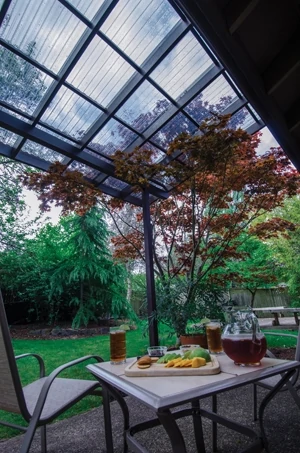
It rains a lot where I live in Oregon, and for the most part we carry on with sporting events, yard work, hikes and graduation ceremonies in the rain. However, we don’t mind a little shelter from the rain when relaxing on a patio. We do not, however, want that shelter to interfere with the bit of sun we get between July and October.
That’s the story behind this patio cover project. Handle the rain while maintaining an open air feel. The plan: Install polycarbonate corrugated sheets high enough to allow for unobstructed views, for plenty of light and for air movement.
Simply attaching to the vertical surface of the wall or even to the fascia board would not be nearly high enough to accomplish these goals. That’s why we looked to SkyLift for hardware that would enable us to securely mount the patio cover structure well above the rain gutter level and slope it for rain runoff without obstructing the view at the lower portion. (Skylifthardware.com)
SkyLift accomplishes this by providing a vertical riser with a flat plate that penetrates the roof and attaches to the top plate of the exterior wall. The top of the riser accepts a saddle designed to support a beam, which supports the house end of the patio cover. A corresponding beam set on posts supports the other end of the patio cover framing.
There are several advantages to the SkyLift design. First, it attaches to the wall framing without interfering with the roof support system. Second, it seals with a standard pipe jack flashing just like the vent pipes you see on most roofs. Third, it provides a way to set the roof beam into place one end at a time. Fourth, it holds the beam securely while allowing lateral adjustments to get the structure square before lag-bolting the beam in place.
Here’s how we built our patio cover, which is now ready for our summer rain.
First we selected a polycarbonate corrugated roofing material that let in light but also provided UV protection. We saw that the sheets were about 12 ft. long and laid up to 24 in. wide (after overlap). We figured a 12-by-12-ft. cover would be about right for the space so we picked up six sheets along with the supporting corrugated moldings.![[01] IMG_8094](https://extremehowto.com/wp-content/uploads/2013/08/01-IMG_8094.webp)
After carefully exploring for irrigation pipes, we determined locations for two 4×4 posts just outside of the patio slab. We dug the post holes 8 ft. apart and made each 2 ft. deep.
![[02] TMW_3075](https://extremehowto.com/wp-content/uploads/2013/08/02-TMW_3075.webp)
We dropped the 4×4 posts into the ground and drove stakes so two 2×4 braces per post could be set with one parallel to the house and the other perpendicular to the house.
![[03] TMW_3100](https://extremehowto.com/wp-content/uploads/2013/08/03-TMW_3100.webp)
We mixed up a batch of Sakrete to set the posts.
![[04] IMG_8110](https://extremehowto.com/wp-content/uploads/2013/08/04-IMG_8110.webp)
We used our 4×4 posts to estimate locations for our two SkyLift roof riser brackets. We removed two pieces of composition shingle (one above the other) at each location for the SkyLift hardware.
![[05] TMW_3220](https://extremehowto.com/wp-content/uploads/2013/08/05-TMW_3220.webp)
We drilled two 1-in. holes through the roof sheeting (one for a flashlight, the other for an eyeball). We used a 2-ft. section of arrow shaft to move the insulation so we could see where we were.
We used a torpedo level to make sure our arrow shaft was straight up and down. At our first location we could see that we were just inside the top plate, so we planned our opening just down the hill accordingly. We had no objects interfering with our hardware.
![[06] TMW_3218](https://extremehowto.com/wp-content/uploads/2013/08/06-TMW_3218.webp)
![[07] TMW_3221](https://extremehowto.com/wp-content/uploads/2013/08/07-TMW_3221.webp)
The base of the SkyLift hardware was the template to mark the opening.
![[08] TMW_3227](https://extremehowto.com/wp-content/uploads/2013/08/08-TMW_3227.webp)
![[09] TMW_3239](https://extremehowto.com/wp-content/uploads/2013/08/09-TMW_3239.webp)
We used our Porter Cable cordless jigsaw to cut out the opening.
We used two ratchet extensions and a socket on our impact driver to lag the SkyLift base to the top plate. We centered the base plate (inside to outside) on the wall’s top plate. The left to right positioning as you look at the house is not that critical because the beams are cantilevered on the hardware.
![[10] TMW_3247](https://extremehowto.com/wp-content/uploads/2013/08/10-TMW_3247.webp)
We slipped a standard pipe jack flashing over the riser column with the top tucked under the roofing above it and the bottom overlapping the lower roofing material.
![[11] TMW_3185](https://extremehowto.com/wp-content/uploads/2013/08/11-TMW_3185.webp)
We replaced the composition shingles that were removed earlier, notching for the pipe jack flashing as needed. We were careful to use roofing tacks only in areas that were not exposed to the weather.
![[12] TMW_3259](https://extremehowto.com/wp-content/uploads/2013/08/12-TMW_3259.webp)
After laying out our roofing material on the lawn using the corrugated molding strips along one edge, we saw that the sheets would be about 145-5/8 inches in both directions. We decided our rafters should be 143-by-143-in. to allow for overhang and a trim strip along the outside edge. We left our 4×6 beams at full length and cut a little chamfer out of the bottom corner of each for looks.
![[13] TMW_3268](https://extremehowto.com/wp-content/uploads/2013/08/13-TMW_3268.webp)
We found that leaving the saddle on the SkyLift riser unbolted allowed one guy to place the end of a beam in the saddle and climb a ladder with the other end. The saddle spins to follow the beam. Nice feature.
![[14_2] TMW_3277](https://extremehowto.com/wp-content/uploads/2013/08/14_2-TMW_3277.webp)
We used a straight rafter to level across from the roof hardware to a 4×4 post. After allowing for 18 in. of fall for water runoff, we marked and cut off one 4×4 post. We leveled over to the other post to mark and cut it to height. We set our one 4×6 beam on the posts and secured by toenailing screws into the posts.
![[15] LDW_7113](https://extremehowto.com/wp-content/uploads/2013/08/15-LDW_7113.webp)
We positioned one rafter with our preferred overhang and used a level to mark the vertical line for a bird’s mouth joint at the outside beam. We used a 3/4 strip on top of the beam to mark the horizontal line. We decided not to cut bird’s mouth joints for the house beam for a couple of reasons, the primary being that the beams were not exactly parallel.
.![[16] LDW_7132](https://extremehowto.com/wp-content/uploads/2013/08/16-LDW_7132.webp)
We used a jigsaw to cut out the bird’s mouth notch in each outside rafter. A cardboard template made a great tool to lay out the notches for the remaining rafters.
![[17] LDW_7138](https://extremehowto.com/wp-content/uploads/2013/08/17-LDW_7138.webp)
We cut the rafters to 140 in. long. With a header across both ends of the rafter tails, this netted the 143 inches we needed for the frame.
![[18] TMW_3291](https://extremehowto.com/wp-content/uploads/2013/08/18-TMW_3291.webp)
After setting the outside beam, we placed the two outside rafters on our 143-in. layout and toe-nailed them to the beams. We then squared the structure by measuring diagonally and shifting the roof beam side to side in the SkyLift saddles to get the diagonal measurements to match.
![[19] TMW_3296](https://extremehowto.com/wp-content/uploads/2013/08/19-TMW_3296.webp)
The SkyLift saddle attaches to the riser with the supplied nut and bolt.
.![[20] TMW_3298](https://extremehowto.com/wp-content/uploads/2013/08/20-TMW_3298.webp)
The SkyLift saddle fastens to the roof beam using the supplied lag screws. An interesting SkyLift design is that the holes on one side of the saddle are off-set from the other side, which prevents the lag screws from colliding in the middle.
![[21] IMG_8180](https://extremehowto.com/wp-content/uploads/2013/08/21-IMG_8180.webp)
After setting the remainder of the rafters on the 24-in. layout, we made 24-in. layout marks down the two outside rafters and snapped chalk lines to set the 2×2 purlins, which run on top of and perpendicular to the rafters.
![[22] TMW_3308](https://extremehowto.com/wp-content/uploads/2013/08/22-TMW_3308.webp)
We nailed corrugated molding on top of the 2x2s, watching the peaks and valleys at the rafters to make sure they were lined up.
![[23] LDW_7171](https://extremehowto.com/wp-content/uploads/2013/08/23-LDW_7171.webp)
We loaded all six sheets of the polycarbonate roofing onto our structure, working from one end to the other.
After lining up the sheets with a consistent 1-in. overhang, we predrilled and fastened each with screws equipped with washers and rubber gaskets along the lower edge of the roof.
![[25] LDW_7175](https://extremehowto.com/wp-content/uploads/2013/08/25-LDW_71751.webp)
We spanned over at least three purlins at a time with plywood to distribute weight so we could screw off the remainder of the sheets. We spaced fasteners at 1-ft. intervals across and 2 ft. up and down, being sure to include the overlaps which fasten down the edges.
![[26] LDW_7198](https://extremehowto.com/wp-content/uploads/2013/08/26-LDW_71981.webp)
We attached the 4×6 beams to the 4×4 posts with custom made 1/8-in. steel straps cut at 3-by-9 inches.
![[27] LDW_7178](https://extremehowto.com/wp-content/uploads/2013/08/27-LDW_71781.webp)
It didn’t take long for our Oregon climate to bring us a rain shower to test our roof. No leaks—thanks to SkyLift’s bright idea of using pipe jack flashing.
Side Note: Pre-Painted
![[28] TMW_3136](https://extremehowto.com/wp-content/uploads/2013/08/28-TMW_31361.webp)
We pre-painted all of the framing lumber with primer and two top coats before we installed it on this project. Be sure to paint the end grain as well, which helps to protect the wood from moisture.